electronics
I searched for "frog juicer" on eBay...
May 24, 2017

Cute, but I can't see where to attach the wires.
Resistance wheels
Sep 18, 2016
If you want signaling on your layout (and who doesn't!), you will need some way of determining block occupancy. I use Bruce Chubb's Optimized Detectors, when are a current sensing-type detector, and they have worked flawlessly on the Mighty MKT for years.
The current sensing detectors can sense the locomotives in a block, but for cabooses and rolling stock, you need to add a resistance wheels set or two on the car to create current path that trips the detectors. We do that by adding a small (and I mean small) surface mount resistor across the axle and the gap on the insulated wheel. The current path is completed using conductive paint.
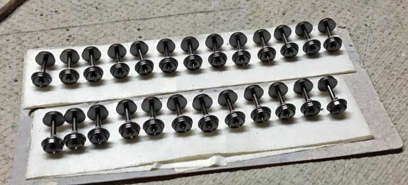
Step one is to layout out several wheels on some masking tape so you can apply the conductive material. You then place a very small amount of CA (superglue) to the insulated side of the axle, and gently place the resistor on the glue, angled across the gap between the axle and the metal portion of the insulated wheel.
After the glue dries, you can then use a fine pick or needle point to add a very small dollop of the conductive paint, first to the wheel side, then to the axle side. In N scale, this is very precise and tedious work, since you need to make sure not to cover the entire resistor with paint, nor submerge the resistor in the drop of CA. My buddy, Joe, is MUCH better at this process than I am.
If you look closely, you can see the axle side of the bottom wheels covered with the conductive paint.
For years, I put conductive wheels only on my cabooses, and used software to "detect" short blocks on the layout. I do not detect the turnouts individually as you would need to do on a full-blown CTC layout. My goal is to gradually add resistance axle to every car 50 ft or shorter, and two (opposite side) axles on all cars longer than 50 ft.
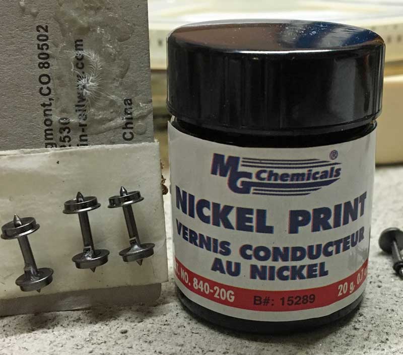
I bought a package of 100 wheels from Fox River Valley, which is a good start toward my goal of at least one detected axle per car on the layout. Three or four more packages and I can call it good!
The current sensing detectors can sense the locomotives in a block, but for cabooses and rolling stock, you need to add a resistance wheels set or two on the car to create current path that trips the detectors. We do that by adding a small (and I mean small) surface mount resistor across the axle and the gap on the insulated wheel. The current path is completed using conductive paint.
Step one is to layout out several wheels on some masking tape so you can apply the conductive material. You then place a very small amount of CA (superglue) to the insulated side of the axle, and gently place the resistor on the glue, angled across the gap between the axle and the metal portion of the insulated wheel.
After the glue dries, you can then use a fine pick or needle point to add a very small dollop of the conductive paint, first to the wheel side, then to the axle side. In N scale, this is very precise and tedious work, since you need to make sure not to cover the entire resistor with paint, nor submerge the resistor in the drop of CA. My buddy, Joe, is MUCH better at this process than I am.
If you look closely, you can see the axle side of the bottom wheels covered with the conductive paint.
For years, I put conductive wheels only on my cabooses, and used software to "detect" short blocks on the layout. I do not detect the turnouts individually as you would need to do on a full-blown CTC layout. My goal is to gradually add resistance axle to every car 50 ft or shorter, and two (opposite side) axles on all cars longer than 50 ft.
I bought a package of 100 wheels from Fox River Valley, which is a good start toward my goal of at least one detected axle per car on the layout. Three or four more packages and I can call it good!
Boonville gets sound!
Jul 25, 2016
I recently completed a nice upgrade to the Union Pacific job at Boonville: adding a stationary sound decoder. The decoder is hard wired to the DCC bus beneath Boonville, and is installed as part of the locomotive consist for the morning shift of the Boonville UP Job. The speaker (from an iPhone) is located inside the Mid-Missouri Processed Foods building, which acts as a resonating chamber for the speaker. The volume is quite loud and high quality.
I use a Soundtraxx Econami ECO-100 diesel decoder, with an iPhone speaker. The iPhone speaker is nice in that the baffle is all built-in, so you just solder the two wires and you are ready to rumble!
One may comment, “But the sound is stationary! It doesn’t follow the locomotive!” Tru’ dat, but the Boonville switching area is relatively compact and the bass frequencies tend to omni-directional in nature, so the directional effect is generally not noticed. You will notice that the bell sounds and the horn effects do not come from the locomotive – not a big deal.
A nice feature of the Econami decoder is the quiet mode time-out period (CV113). When the throttle is set to zero and all functions are off, all sound effects will automatically deactivate after the quiet mode time-out period elapses. I have the time out period set to 30-45 seconds, so when the locomotives are idle, the sound will cease. This prevents the consist from idling and popping all during the session in staging.
The long-term goal is to install another decoder and speaker for the PM shift locomotives, and install it in the same location.
Let there be (LED) light!
Jun 18, 2016
The last few days have been busy with some final projects before I start cleaning the layout in preparation for the N-scale Convention tours and operating sessions.
I wanted to add some lighting the ACF Car Repair buildings at East St. Charles.
The lights turned out great and I wanted to share my method for installing the LEDs. It's not rocket science, but you may find a tip or two here.
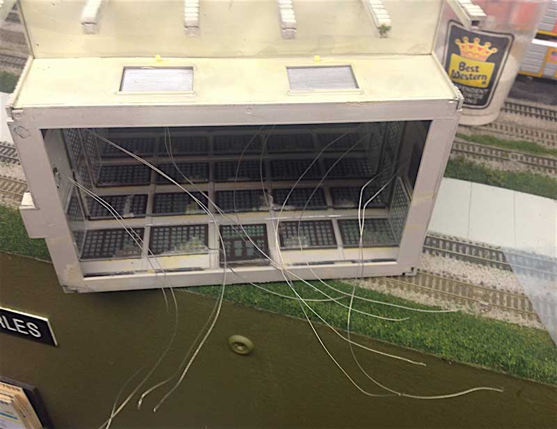
Step 1 - buy the pre-wired LEDs off eBay (free shipping from China!) and install in the buildings. I just drill a small hole at the location, thread the wires in and secure in place with a tiny dab of super glue. A quick shot of CA accelerator, and the LED is secure.
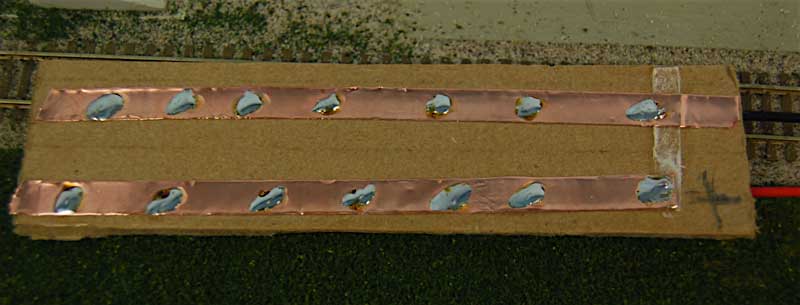
Step 2 - I make an electrical bus with copper strips that are used for stained glass windows. It has an adhesive backing and takes solder REALLY well. I also use wiring connector plugs (from eBay) that allow me to building these things at the work bench, then plug them into a 12 volt supply from under the layout. Both the positive bus and the ground bus are tinned where I will land the resistors and the wires.
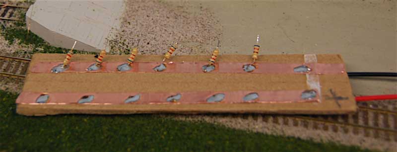
Step 3 - I trim the leads from the resistors and solder into place. The resistor leads going to the bus don't need to be tinned, but I tin the free ends, because it makes the next step a LOT easier. The resistors values have been selected to provide good intensity with a 12 volt supply.
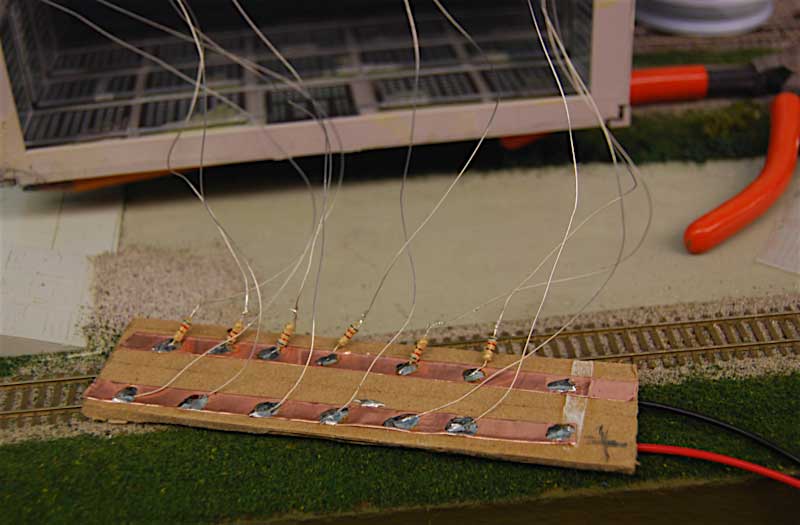
Step 4 - I then tin the wires from the LEDs, being mindful of which wire is the positive (these are light emitting diodes, right, so polarity is important). I land the wires. At the positive bus, the wires attach very easily and quickly. For the resistor side, I use the "Kasper paralllel soldering method", where the two wires are tinned, held parallel, heated simultaneously, then held precisely in place while the solder cools. This technique requires a steady hand, and tinning the wires beforehand is crucial. I'm getting better at it.
Elite Operator™ tip! It doesn't matter if the resistors go before the LEDs or after the LEDs in the circuit. Just sayin'.
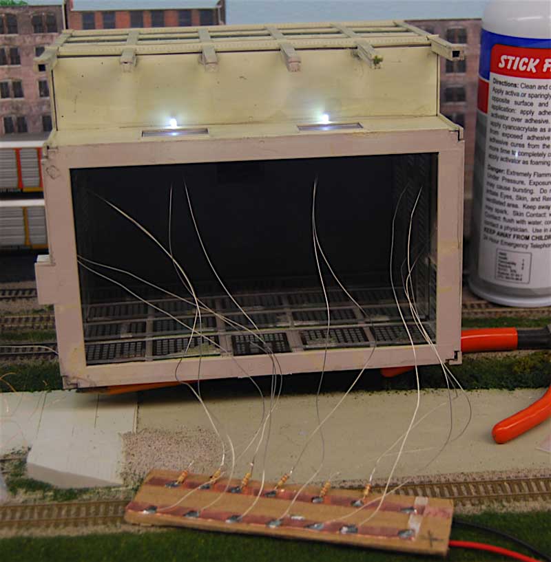
Step 5 - Test the wiring (I have a battery pack with a connecting plug to help with this step.
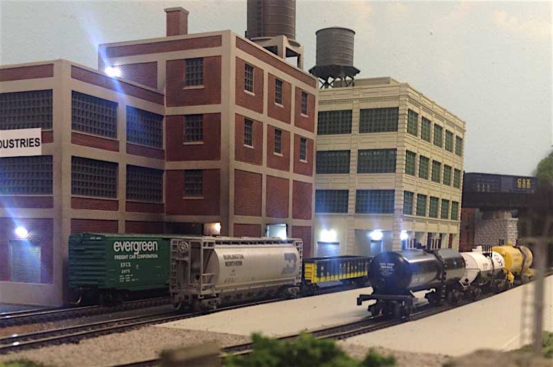
VOILA! Yummy lighting goodness! I think lighting really adds to the scene. These LEDs are cool white - they also sell a "warm white" version that I like a bit better. I may warm these LEDs up a bit with a dab of Tamiya clear tinted paint.
I wanted to add some lighting the ACF Car Repair buildings at East St. Charles.
The lights turned out great and I wanted to share my method for installing the LEDs. It's not rocket science, but you may find a tip or two here.
Step 1 - buy the pre-wired LEDs off eBay (free shipping from China!) and install in the buildings. I just drill a small hole at the location, thread the wires in and secure in place with a tiny dab of super glue. A quick shot of CA accelerator, and the LED is secure.
Step 2 - I make an electrical bus with copper strips that are used for stained glass windows. It has an adhesive backing and takes solder REALLY well. I also use wiring connector plugs (from eBay) that allow me to building these things at the work bench, then plug them into a 12 volt supply from under the layout. Both the positive bus and the ground bus are tinned where I will land the resistors and the wires.
Step 3 - I trim the leads from the resistors and solder into place. The resistor leads going to the bus don't need to be tinned, but I tin the free ends, because it makes the next step a LOT easier. The resistors values have been selected to provide good intensity with a 12 volt supply.
Step 4 - I then tin the wires from the LEDs, being mindful of which wire is the positive (these are light emitting diodes, right, so polarity is important). I land the wires. At the positive bus, the wires attach very easily and quickly. For the resistor side, I use the "Kasper paralllel soldering method", where the two wires are tinned, held parallel, heated simultaneously, then held precisely in place while the solder cools. This technique requires a steady hand, and tinning the wires beforehand is crucial. I'm getting better at it.
Elite Operator™ tip! It doesn't matter if the resistors go before the LEDs or after the LEDs in the circuit. Just sayin'.
Step 5 - Test the wiring (I have a battery pack with a connecting plug to help with this step.
VOILA! Yummy lighting goodness! I think lighting really adds to the scene. These LEDs are cool white - they also sell a "warm white" version that I like a bit better. I may warm these LEDs up a bit with a dab of Tamiya clear tinted paint.
The pull-up resistor
Jun 14, 2016
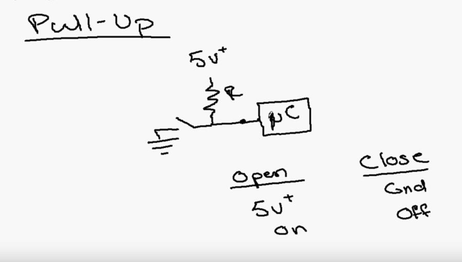
I've been working on some arduino circuits and decided to take a break to learn a bit about pull-up resistors, which are used in a digital circuits to prevent floating conditions when dealing with inputs.
As usual, a quick search on the google provided a ton of information on the subject. Here is a great video that I found on the youtubes:
Series vs Parallel Resistors
May 21, 2016
I always need to look this up, so I am posting it here in case anyone else finds it useful (you Elite Operators™ probably already have it memorized)
And, while we're at it, here's an Ohm's Law cheat sheet that I've often found useful:
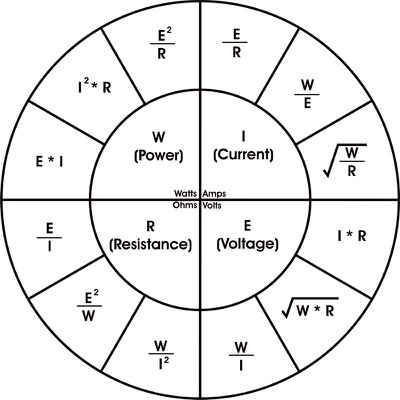
And, while we're at it, here's an Ohm's Law cheat sheet that I've often found useful: