The Missouri-Kansas-Texas (MKT) St. Louis Subdivision is an N-scale layout of a segment of a prototype railroad. The St. Louis Subdivision models the real world from Boonville, Missouri to St. Charles, Missouri, generally following the Missouri River as it snakes across central Missouri.
The layout is a single deck point-to-point style, with emphasis on operation. The layout incorporates off-site staging to enable trains to pass through the scenicked portion of the layout, then back to the staging area, embracing Allen McClelland's "beyond the basement" concept.
The layout has over 140 ft of scenicked main line, over four scale miles. Operation of the layout is enhanced by Bruce Chubb's Computer/Modeling Railroad Interface (C/MRI), which handles the signaling, turnout control, and block assignments used during operating sessions. A computer monitor dispatching display is used to select and monitor block occupation, cab assignment, train speed, and turnout condition.
Layout Orientation
The layout is conceptually very simple: Imagine two forks laid top to top, with the tines pointing out. That is the MKT, St. Louis Subdivision! The left (or west) tines represent Sedalia Staging and the right (or east) tines represent Baden Yard in St. Louis, the eastern staging. The stems of the two forks represent the modeled portion of the layout.
The modeled portion of the layout is linear and sincere, which means that the main track doesn't wrap back on itself, and that the track goes through a scene only once.
When you face the layout, north is always toward the wall, so west is left and east is right. From New Franklin to St. Charles, the track runs along the Missouri River, so we like to say that an operator is standing in the river when running trains in the layout room!
After the landforms were created and the towel-plaster and plaster sub ground were applied the ground cover was installed. I followed Dave Frary’s water soluble method of scenery, as outlined in his excellent book. Another good reference is the Woodland Scenics book.
The first step in applying ground cover is to paint the ground surface with a tan latex paint. I usually gave the surface two coats, since the first coat tended to get soaked up by the plaster and dried faster than I could apply the ground cover.
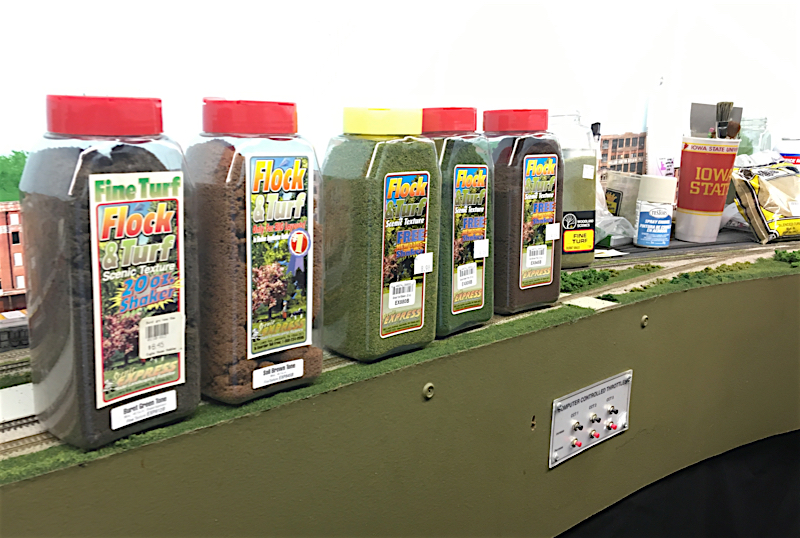
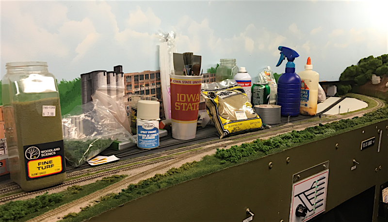
The second coat of paint is applied rather thick, in order to stay wet for the next step. Fine ground foam (Woodland Scenics fine turf) was sprinkled on the ground surface immediately after the second coat of tan paint is applied. I usually worked with a two- to three square foot area at a time. Several shades of the fine turf material were applied in overlapping layers. I have several shaker bottles, mostly home-made (nail holes punched in the lids of peanut butter jars), each filled with a different shade of the fine turf material. I tend to use the darker greens and browns, and skip the lighter and yellow shades. . The final layer of turf material is usually burnt grass, as I feel that this shade tends to blend the other shades and hide any extreme shade changes in the ground cover. When the ground cover looks right, I wet the area with rubbing alcohol (in a spray bottle), and then spray the area with Woodland Scenics Scenery Cement or a potion of 50 percent diluted white glue (with a few drops of detergent). The application of the rubbing alcohol serves to break the surface tension of the glue, enabling the glue to penetrate the ground cover. Figure 1 shows an example of the ground cover.
Since the landscape of the prototype St. Louis Sub was generally forested and largely overgrown, I add clumps of ground foam of various sizes and shades to the ground cover. Again, I tend to stay away from the lighter and brightly colored shades, sticking with the deep greens and browns. I use small (rice sized) bits to represent the low shrubs that existed along the track roadbed. Larger (marble sized) pieces are placed at the approximate extent of the railroad right-of-way, representing the limits of railroad maintenance and the beginning of the forest undergrowth found in the area.
The ground foam clumps are used liberally throughout the scenery, representing the non-cultivated or maintained areas. Often, these foam bushes are the final step in the scenery, especially in those areas where access is important (as near industrial areas) and larger trees may be destroyed or create an obstruction during operating sessions.
The final step for the ground cover is to wet the foam clumps with the alcohol and apply diluted white glue onto the scenery. The glue is readily soaked into the foam, and hardens to a resilient mass of scenery! Sometimes several applications of the glue are necessary before the scenery is sufficiently attached.
The first step in applying ground cover is to paint the ground surface with a tan latex paint. I usually gave the surface two coats, since the first coat tended to get soaked up by the plaster and dried faster than I could apply the ground cover.
The second coat of paint is applied rather thick, in order to stay wet for the next step. Fine ground foam (Woodland Scenics fine turf) was sprinkled on the ground surface immediately after the second coat of tan paint is applied. I usually worked with a two- to three square foot area at a time. Several shades of the fine turf material were applied in overlapping layers. I have several shaker bottles, mostly home-made (nail holes punched in the lids of peanut butter jars), each filled with a different shade of the fine turf material. I tend to use the darker greens and browns, and skip the lighter and yellow shades. . The final layer of turf material is usually burnt grass, as I feel that this shade tends to blend the other shades and hide any extreme shade changes in the ground cover. When the ground cover looks right, I wet the area with rubbing alcohol (in a spray bottle), and then spray the area with Woodland Scenics Scenery Cement or a potion of 50 percent diluted white glue (with a few drops of detergent). The application of the rubbing alcohol serves to break the surface tension of the glue, enabling the glue to penetrate the ground cover. Figure 1 shows an example of the ground cover.
Since the landscape of the prototype St. Louis Sub was generally forested and largely overgrown, I add clumps of ground foam of various sizes and shades to the ground cover. Again, I tend to stay away from the lighter and brightly colored shades, sticking with the deep greens and browns. I use small (rice sized) bits to represent the low shrubs that existed along the track roadbed. Larger (marble sized) pieces are placed at the approximate extent of the railroad right-of-way, representing the limits of railroad maintenance and the beginning of the forest undergrowth found in the area.
The ground foam clumps are used liberally throughout the scenery, representing the non-cultivated or maintained areas. Often, these foam bushes are the final step in the scenery, especially in those areas where access is important (as near industrial areas) and larger trees may be destroyed or create an obstruction during operating sessions.
The final step for the ground cover is to wet the foam clumps with the alcohol and apply diluted white glue onto the scenery. The glue is readily soaked into the foam, and hardens to a resilient mass of scenery! Sometimes several applications of the glue are necessary before the scenery is sufficiently attached.
Design Philosophy
DESIGN PHILOSOPHY
The model parameters that I kept in mind during the layout design for the MKT St. Louis Subdivision are summarized below. These parameters are what John Armstrong refers to as "Givens and Druthers." The layout employs Allen McClelland's "Good Enough" philosophy. (this is primarily a reflection of my modeing skills!)
The track plan is relatively simple, like the prototype. I call this the "anti-spaghetti bowl" concept. Where possible (and where available), I duplicated the prototype trackage, emphasizing simple siding arrangements, a single main line, simple industry trackage (no switching puzzles), and no hidden track in the train room. There is a short stretch of hidden staging yard approach track behind the furnace.
Guiding Design Parameters:
Track:
The model parameters that I kept in mind during the layout design for the MKT St. Louis Subdivision are summarized below. These parameters are what John Armstrong refers to as "Givens and Druthers." The layout employs Allen McClelland's "Good Enough" philosophy. (this is primarily a reflection of my modeing skills!)
The track plan is relatively simple, like the prototype. I call this the "anti-spaghetti bowl" concept. Where possible (and where available), I duplicated the prototype trackage, emphasizing simple siding arrangements, a single main line, simple industry trackage (no switching puzzles), and no hidden track in the train room. There is a short stretch of hidden staging yard approach track behind the furnace.
Guiding Design Parameters:
- Relatively long stretches of single track to facilitate the through train running experience.
- Interchange and off-layout staging was incorporated into the operating scheme to enhance the "beyond the basement" concept.
- Franklin Yard to be a reasonably-sized classification yard with a diesel servicing facility and shops area.
- A mainline sufficiently long to have at least four passing sidings, in addition to the classification yard.
- The railroad passing through a scene only once (called a "sincere" layout track plan by some).
Track:
- Main line and sidings: Microengineering Code 55 flextrack
- Staging yard: Atlas flextrack and turnouts
- Main line turnouts: Microengineering Code 55 #6 turnouts
- Minimum radius - Visible mainline and passing sidings: 24"
- Minimum radius - Non-visible mainline and passing sidings: 20"
- Track center spacing to be 1.25 to 1.5" (1.25" in yards or straight track)
- Mainline/passing sidings/crossovers: #6
- Yards: #6
- Industrial trackage: #4 (seldom used)
- Micro Engineering Code 55 flextrack and turnouts
- Some Peco Code 55 turnouts
- Maximum: 1 percent (this particular segment of the MKT route had some of the flattest track in the country: 88 feet of elevation change over a distance of 187 miles)
- Nominal train length: 11 feet (3 locomotives, 30 fifty-foot cars and a caboose)
- Major passing sidings and staging tracks set at 11 feet (NOTE: A siding/staging track length of 11 feet has proved to be a difficult criteria to achieve! My first design consisted of one passing siding following another, so I eliminated one town (siding) to provide for more single trackage. Although I hated to delete Rocheport, with its beautiful scenery and the only tunnel on the entire MKT railroad, it had to go! And I think that the layout is better because of it).
- Walk-in and walkaround layout
- The nominal aisle width is 36", and I worked hard to maintain this width. A support beam column requires a tight aisle for about 6", but it hasn't proven to be a problem. Yet.
- No on-layout reach greater than 24"
- Layout benchwork height is 53"
- Benchwork depth ranges from 12" to 24"
- Sectional benchwork was chosen because I wanted to have the option to salvage at least the benchwork if a move was necessary. The sections are built from 1 ft x 4 ft frames with 1/2 inch plywood tops. There are several 2 ft by 4 ft sections, a couple of 1 ft by 8 ft sections, and a few oddball corner/transition sections.
- The benchwork sections are lag screwed to the wall risers, leveled with the support arm, and bolted together. The resulting benchwork is very strong!
- DCC train control, using CPV’s EasyDCC, with a combination of wireless (8) and tethered (5) throttles
- Block detection and signal function are controlled via Bruce Chubb's Computer/Model Railroad Interface.
- Dispatching is accomplished through the use of a CRT console, tied into the C/MRI. Train movement and signal aspect are monitored on the screen. Staging tracks are via a virtual matrix with on-screen mouse clicks
Scenery
Scenery on the MKT, St. Louis Subdivision
THIS SECTION IS UNDER CONSTRUCTION…
A variety of scenery construction methods were used to create the scenery on the St. Louis Subdivision of the Missouri-Kansas-Texas (MKT) Railroad. This document will summarize the types of scenery found on the layout and discuss the scenery methods used.

Overview
click for slideshow
- extensively forested areas along the bluffs that create the northern extent of the Missouri River valley
- flat Missouri River alluvial valley, usually cultivated (when not flooded)
- scrub forest undergrowth found on both sides of the railroad right-of-way
- river bank and Missouri River water features
Oak and walnut trees predominate in this area, with some mature trees growing well over 100 feet. Near the river, tall cottonwood trees are common with dense undergrowth extending from the maintained railroad right-of-way to the river's edge.

Landforms and Contours
click for slideshow
The blue or pink closed cell foam works much better, in my opinion. For either foam types, I stacked several layers, glued them together, and carved the foam with a kitchen knife to the approximate shapes desired.
After the basic shapes were created, paper towels, dipped in plaster or hydrocal, were applied to the foam to create a smoother ground surface. In areas where rock outcrops were desired, plaster rock, created from molds, were hot glued to the foam and towel base.
Plaster "subground" was applied in many areas to get rid of the flat plywood look. In several areas, the fascia was cut in an undulating fashion, and plaster was applied between the benchwork and the fascia to create realistic landforms.

Ground Cover
click for slideshow
The first step in applying ground cover is to paint the ground surface with a tan latex paint. I usually gave the surface two coats, since the first coat tended to get soaked up by the plaster and dried faster than I could apply the ground cover.
The second coat of paint is applied rather thick, in order to stay wet for the next step. Fine ground foam (Woodland Scenics fine turf) was sprinkled on the ground surface immediately after the second coat of tan paint is applied. I usually worked with a two- to three square foot area at a time. Several shades of the fine turf material were applied in overlapping layers. I have several shaker bottles, mostly home-made (nail holes punched in the lids of peanut butter jars), each filled with a different shade of the fine turf material. I tend to use the darker greens and browns, and skip the lighter and yellow shades. . The final layer of turf material is usually burnt grass, as I feel that this shade tends to blend the other shades and hide any extreme shade changes in the ground cover.
When the ground cover looks right, I wet the area with rubbing alcohol (in a spray bottle), and then spray the area with Woodland Scenics Scenery Cement or a potion of 50 percent diluted white glue (with a few drops of detergent). The application of the rubbing alcohol serves to break the surface tension of the glue, enabling the glue to penetrate the ground cover. Figure 1 shows an example of the ground cover.
Since the landscape of the prototype St. Louis Sub was generally forested and largely overgrown, I add clumps of ground foam of various sizes and shades to the ground cover. Again, I tend to stay away from the lighter and brightly colored shades, sticking with the deep greens and browns. I use small (rice sized) bits to represent the low shrubs that existed along the track roadbed. Larger (marble sized) pieces are placed at the approximate extent of the railroad right-of-way, representing the limits of railroad maintenance and the beginning of the forest undergrowth found in the area.
The ground foam clumps are used liberally throughout the scenery, representing the non-cultivated or maintained areas. Often, these foam bushes are the final step in the scenery, especially in those areas where access is important (as near industrial areas) and larger trees may be destroyed or create an obstruction during operating sessions.
The final step for the ground cover is to wet the foam clumps with the alcohol and apply diluted white glue onto the scenery. The glue is readily soaked into the foam, and hardens to a resilient mass of scenery! Sometimes several applications of the glue are necessary before the scenery is sufficiently attached.

Cliffs and Rock Outcrops
click for slideshow
In one area (Rocheport, see Figures 4 and 5), I needed a long stretch of vertical rock. In this area I placed several plaster rocks oriented different directions to eliminate the copycat look, and used plaster slurry to connect the various plaster rocks.
The rocks are weathered with several applications of tinting agents (diluted acrylic paints and India ink washes). The weathering occurs over several work sessions, since the rock tends to lighten as it dries.
After weathering is completed, I apply crushed rock to the base of the plaster rocks to imitate the weathered talus that tends to accumulate below the outcrops. A bit of vegetation, placed on the vertical surfaces, completes the look.

Trees and Vegetation
click for slideshow
The kit trees are made from commercial kits, including the Woodland Scenics trees, and "Super Trees" by Scenic Express. The Woodland Scenics kits contain plastic tree trunk structures, and the user affixes ground foam with adhesive. These trees are quick, easy, sturdy, and realistic. They may be slightly more expensive on a per tree basis than the scratch-built versions, but their convenience is worth it to me. The Super Trees are similar to the other kit trees, but use a natural plant as the trunk and limb armature.
The kit trees are placed in the foreground, and in places where a single tree would be noticed by the observer.
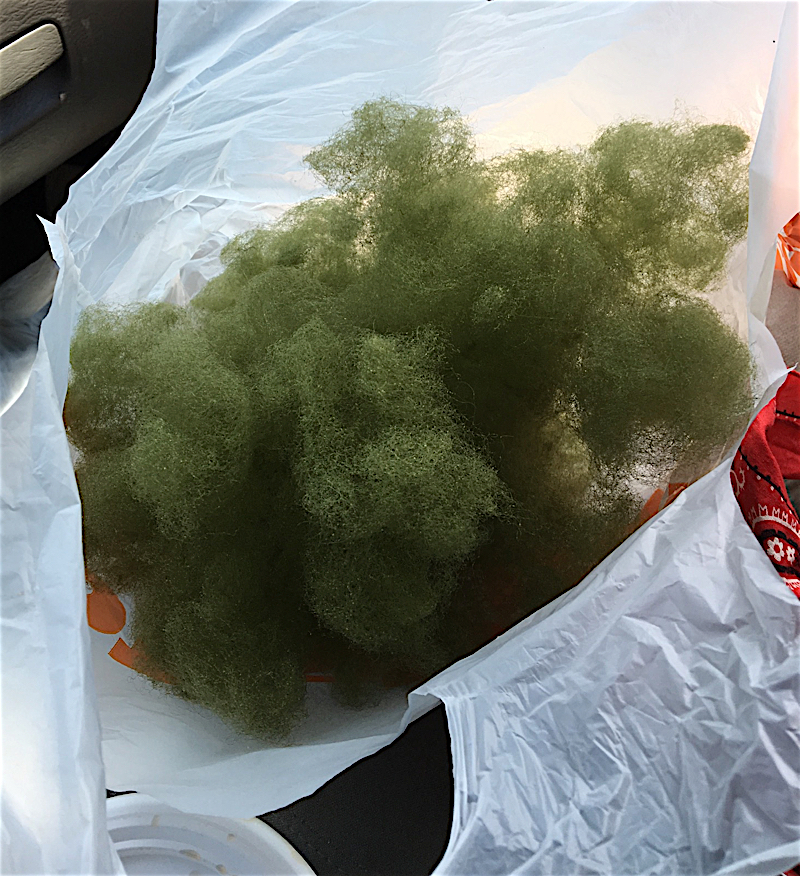
The Koester trees are used in places where a forest canopy is desired. These trees are essentially polyfiber spheres, coated with black spray paint and covered with ground foam. I use the Woodland Scenics pre-tinted poly fiber, teasing it into a sphere a little larger than a golf ball. I usually create a batch of spheres, making boxes full while watching TV. Taking them outside I latch onto a sphere with tweezers and spray it thoroughly with the spray adhesive. I then roll the painted sphere in a box of ground foam and set the newly created tree aside to dry.
The Koester trees are "planted" on bare, painted subground surface using hot glue or contact cement. The trees are placed closely together, creating the impression of a heavily forested area.

Water
click for slideshow
On the layout, water is represented with several coats of acrylic paints (dark greens, deep blues, and black). The intensity of the colors are varied at the river approached the riverbank, in an attempt to represent the shallower water near the river's edge. The surface of the river is painted with several coats of acrylic gloss medium, providing a shiny surface. An example of river scenery is shown in Figure 11.

Lighting
click for slideshow
For the day lighting, fluorescent lighting was used in the train room. Fluorescent light was selected over incandescent light because of its cost-effectiveness and lack of heat generation. Readily available four foot, two-tube shop lights were installed end-to-end around the perimeter of the train room, angled toward the back wall and hidden behind a lighting valence. In each shop light, a cool white bulb is paired with a warm pastel bulb to provide a warmer light to the scenery.
The end-to-end configuration of the shop lights around the perimeter of the layout room, parallel to the track, results in an even distribution of light. At corners or right angle turns, the lights were spaced so that hot spots were minimized.
The night lighting circuit is a fun addition to the layout. While we don’t yet use the night lights during operating sessions, the long-term goal is to schedule evening through trains once a sufficient amount of structure and city lighting has been installed.
The original lights for the night lighting were separate incandescent bulbs, sold as party light at the hardware stores. I built numerous fixtures, with heat shades and light baffles. When installed, the results were disappointing, because the individual lights created annoying hot spots on the backdrop. I wanted a more consistent lighting environment.
The solution was to use strings of frosted Christmas trees lights, installed parallel to the track work around the perimeter of the layout room. Installation was simple and fast: a few strings of lights, a staple gun and VOILA! Instant night lighting! I had previously installed electrical sockets for the night (and day) circuit in the ceiling area. Since the lighting is comprised of numerous low Wattage bulbs, the heat produced is minimal, and the lighting intensity is consistent throughout the layout room. No hot spots are created, simply a cool blue glow. The layout room required only three strings of lights, which I purchased the week after Christmas.

Backdrop
click for slideshow
The backdrop was painted with a white wall primer, a step that seemed frivolous at the time. However, priming the backdrop resulted in a more even application of the final blue paint layer. I now encourage others to not skip the primer step. Both the primer coat and the blue coat were applied with rollers.
The blue coat is a single color top to bottom. I had considered using blue on the top and white on the bottom, blending the two colors at the horizon. After consideration of the amount of backdrop I had to paint, however, I decided to use the roller method and go with a single shade of blue.
The selection of the blue color was the subject of much debate among my railroad modeling friends and in the railroad modeling literature. I chose a sky blue that seemed to be appropriate when viewed under the fluorescent lighting. I am generally happy with my selection, although the blue tends to wash out in photographs taken of the layout.
I haven’t had many comments about the backdrop, which I consider a success, since I don’t want the backdrop to stand out or be particularly unusual in any respects. I want the backdrop to fade into the background and not draw attention to itself. Faint clouds were added using stencils and white spray paint, which worked well.
C/MRI
C/MRI
The Computer/Model Railroad Interface
The Computer/Model Railroad Interface (C/MRI) is a computer data acquisition system that can be used to control the operation of model railroads. It is not DCC, but can be used in conjunction with DCC.
Put most simply, the C/MRI reads input devices (switch positions, push-button status, block occupation status, throttle direction), makes decisions about the layout based on a user-defined set of parameters (generates signal aspects, block/cab assignments), then sends output commands to devices on the railroad (signal LEDs, turnout machines, block power assignments).
On the MKT, St. Louis Sub, the C/MRI is used to read block occupancy, drive trackside signals, select the staging track turnouts, and display the dispatching console. Unattended operation is also possible, but not used during operating sessions.
The C/MRI was designed by Bruce Chubb, and was presented in a 16-part series of articles in Model Railroader in the mid-80s. The system has proven very popular for both model railroad and non-model railroad applications.
For a complete explanation of the C/MRI, see the February 1985 through August 1986 issues of Model Railroader, or consult Bruce Chubb's book, Build Your Own Universal Computer Interface (Second Edition, ISBN 0-07-922639, 1997). The JLC Enterprises web site describes the many applications of the C/MRI and provides information on building a C/MRI system.
Wikipedia has a good discussion of the C/MRI with several links