Torti installation tips for the Elite Operator™
Here are some tortimus installation tips from my buddy, Joe, a certified Elite Operator™

- Throw rod wire size: 0.039 inches (note: this is sufficient for code 55 track, where you are physically bending the turnout points, as in the amazing Kasper MKVII Rev 2 turnouts)
- Screw size for tortimus installation: #4 and of sufficient length to hold into the subroadbed material
- You only need two screws, placed diagonally on opposite sides, to sufficiently hold the tortimus
- You can use thin double-sided tape to hold the tortimus in the correct position while you place the screws (but only if nobody will see you do it…sign of weakness)
- Drill bit size for the throw rod hole: 3/32 inches. Drill 3-4 holes and ream the slot.
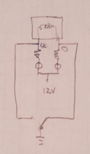
- Resistor for tortimus operation: 470 ohm, 1/2 watt. This assumes a 12 volt power supply
- A single pole double throw turnout toggle is used to throw the turnout (using the Elite Operator™ method of grounding one side of the tortimus, as shown in the figure)
Bonus Elite Operator™ tip!
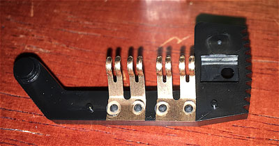
We Elite Operators™ always crack open every (EVERY!) tortoise and flex the spring contacts inward to provide consistent electrical contact. It like the Fram oil filter guy used to say on TV: Pay me now or pay me later!